MainPage:Nuclear:Summer2017:Casey
Impact of surface and reflector on crystal light uniformity
Abstract
A representation of the proton's inner structure requires one to describe orbital angular momentum, an important aspect for nucleon spin, for which one needs to describe the correlation between the momentum and spatial coordinates. A 3D description of the nucleon has been developed through the Generalized Parton Distributions and the Transverse Momentum-Dependent parton distributions. The nucleon tomography as enabled by the Neutral Particle Spectrometer (NPS) in Hall C at Jefferson Lab is an important aspect. One of the components of the NPS is a lead-tungstate (PWO) crystal calorimeter. Important elements for detector resolution are the combination of high and uniform light output and radiation hardness of the crystals. A critical part is the choice of reflector and its placement along the crystal surface, which impact systematic effects like nonlinearities in light collection. To optimize the reflector, different materials including Teflon and ESR were used and their effect on crystal Light Yield compared. The crystal-to-crystal variation of the light yield was also studied. I will present results of reflector material optimization.
Introduction
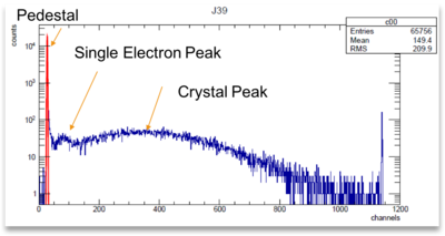
Lead Tungstate Crystals are ideal to use for the NPS because of their small Moliére radius, short radiation length, high density, and radiation hardness. Specifically, the high density results in a higher light yield than other heavy crystals. Light yield is defined as the number of photoelectrons per mega electron volt, and is an important characteristic for the crystals used in the NPS. They crystals must have a light yield of at least 10 pe/MeV, but ideally would be around 15 pe/MeV. Light yield is calculated using the graph and equation shown below.
For the main part of my work, I studied the effect of different reflectors and number of layers on the light yield on PWO crystals. In the NPS detector, it is important to have a consistent and high light yield. Up until this point, all tests had been conducted using 3 layers of Teflon Tape, and I wanted to investigate and try to find a reflector that works better with the crystals. For example, I tested both specular and diffuse reflectors and observed the differences between the two. In addition, I wanted to learn more about the characteristics of the crystals and what sections of the crystals are most important for the light yield.
Summary of results at beginning of summer 2017
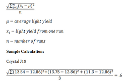
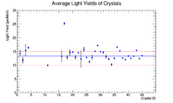
I collected all of the Light Yield results for all crystals and found an average light yield for each crystal. The majority of the crystals had multiple trials, and I used those trials to calculate the least mean squared uncertainty. See picture of calculations for example. The solid blue line is the horizontal line of best fit through the data, indicating the average light yield of all crystals combined. The dotted red lines are at 10 pe/MeV and 15 pe/MeV. The crystals must have a light yield of at least 10pe/MeV, and ideally greater that 15pe/MeV. J11 is the only crystal with a light yield below 10pe/MeV. J17 has a light yield of 25.18 pe/MeV, which is too high. Ideally, all crystals would have a similar light yield, and the data for J11 is much higher than the other crystals.
Fixing the Double Peak
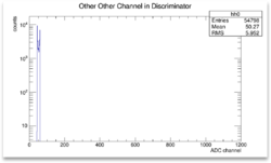
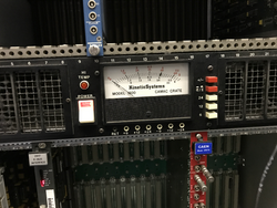
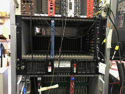
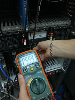
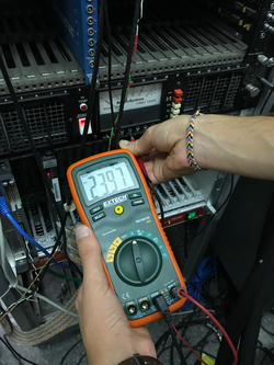
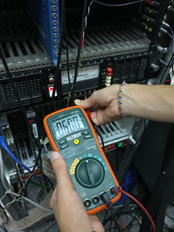
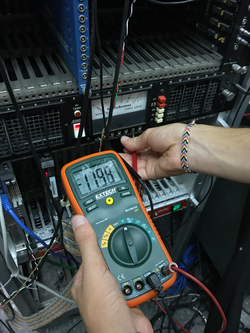
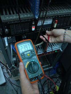
One of the obstacles I encountered was a double peak in the Light Yield data. We tried several different set-ups to discover the source of the off set, and are still investigating. However, the off-set is very small in comparison to the whole graph, and therefore the data is still significant, and the error is reflected in the uncertainties. One of the tests we conducted to was to measure the voltage in the CAMAC crate looking for any fluctuations. See below for pictures of the results and an example of the double peak:
Reflectivity of Materials
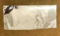
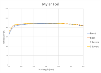
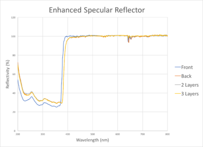
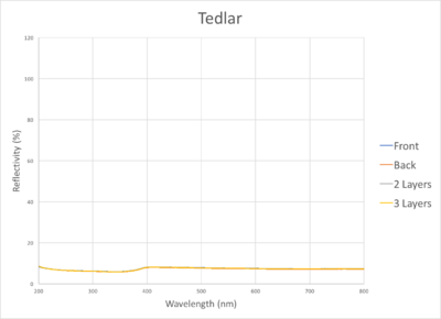
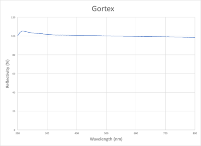
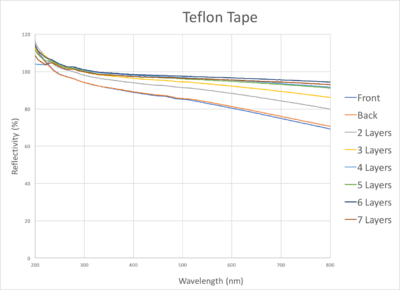
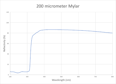
I am comparing three different reflectors to see which material, or combination of materials, will produce the highest and most consistent light yield results. My first step was to use the spectrometer and test the reflectivity of small samples of different reflective materials to get an idea of which materials would be most effective as a reflector when used to collect data on the light yield of crystals. I also tested multiple layers of the materials to see if that improves reflectivity. The wavelengths between 400-500 nm are significant for light yield, specifically 420 nm.
| Material ID | Picture | Material Characteristics | Reflectivity Graphs | |
|---|---|---|---|---|
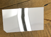
| Mylar Foil | Specular reflector, flimsy (wrinkles easily) | |||
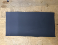
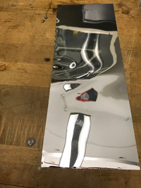
| Enhanced Specular Reflector | Specular reflector | |||
| Tedlar | Commonly used to block out light, not as a reflector | |||
| Gortex | Diffuse reflector, thick and rubbery | |||
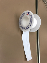
| Teflon Tape | Diffuse reflector, slightly transparent, flexible and easy to wrap crystals with | |||
| 200 micrometer Mylar | Specular reflector |
Light Yield Set-Up
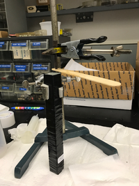
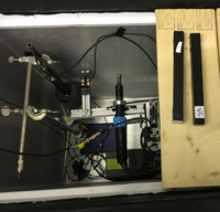
The crystals were wrapped with the reflector being tested, and then an additional two layers of black electrical tape. This covered all faces except one of the ends. Optical grease was applied to the open face of the crystal to connect it to the photo multiplier tube (PMT). We noticed that the amount of optical grease can affect the light yield results. In order to apply a consistent amount for each trial, we made the set-up pictured below. I put some optical grease on the face of the crystal, and then used the popsicle stick to wipe off any excess grease. This kept the amount of grease fairly constant.
The light yield testing was conducted inside a freezer to ensure everything remained at a constant temperature. The crystals were placed in the freezer for at least 20 minutes prior to testing. Each test ran for ~50,000 events.
Description of the crystal light yield measurements with new reflectors
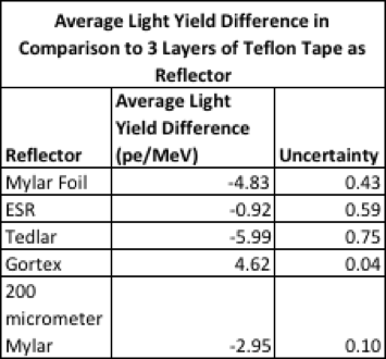
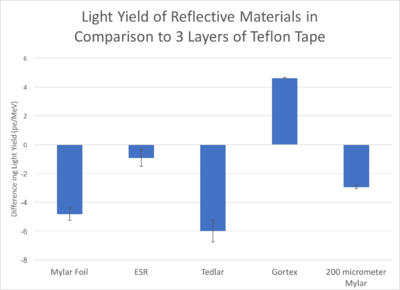
I wrapped the crystals in these different reflectors to observe the effects on light yield. To save time, I used several different crystals. In order to compare the measurements taken with different crystals, I compared all results to the average light yield of each crystal when wrapped with 3 layers of teflon tape. For example (these are arbitrary numbers to explain the process), if J16 had an average light yield of 15 pe/MeV when wrapped with 3 layers of teflon tape, and a light yield of 13 pe/MeV when wrapped with ESR, the difference is -2 pe/MeV. If I use this same process for the data collected using a different crystal and a different reflector, I can compare the two results to see which reflector had the greatest negative impact on light yield in comparison to when the crystals are wrapped with 3 layers of Teflon Tape. The graph below shows the results from testing the light yield of the above materials.
As you can see, Tedlar is the least effective material to use as a reflector. This was the expected result based on the reflectivity graphs and that Tedlar is commonly used to block out light. Mylar Foil, 200 micrometer Mylar, and ESR all produced lower light yields than 3 layers of Teflon Tape. ESR had a higher reflectivity than Teflon Tape at 420 nm, yet was less effective for light yield. This is most likely because Teflon Tape is a diffuse reflector, while ESR is a specular reflector indicating that diffuse reflectors are the most effective when used with these crystals. Gortex had the highest reflectivity at 420 nm, and the highest Light Yield results.
Effect of the number of layers of Teflon Tape on the light yield
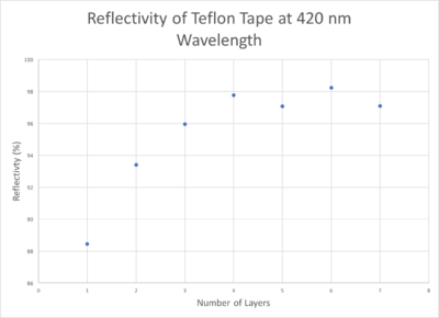
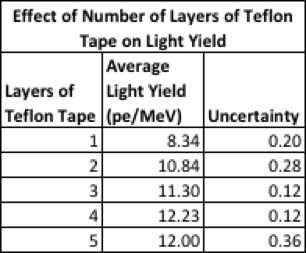
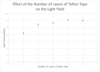
As shown in the reflectivity graph for Teflon Tape, it is slightly transparent and therefore additional layers increase the reflectivity. This trend stops at five layers where the reflectivity appears to plateau. This led me to test if the trend was the same with light yield results. Using the same crystal, I wrapped it in 1-5 layers of Teflon Tape, and compared the average results.
There is a clear positive trend for up to four layers, where the light yield increases as the number of layers increase. At five layers, the light yield decreased, consistent with the reflectivity results. Due to time limitations, I was not able to test higher number of layers, but it appears that the light yield results follow the same trend as the reflectivity results. Four layers of teflon tape is the optimum amount, with anything more having little effect on the light yield.
Investigating the importance of reflectors at different locations on the crystal
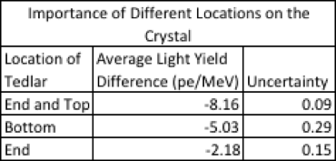
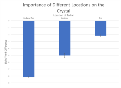
I also wanted to investigate the way that the crystals reflect and multiply the photons. To do this, I decided to test what parts of the crystals are most important for light yield results. Using a combination of Tedlar (low reflectivity, designed to block out light) and 3 layers of teflon tape (good reflector) I was able to observe what section of the crystal has the greatest effect on light yield. I wrapped a section of the crystal in Tedlar, and the rest in Teflon tape. I used three different sections for reflectors: the bottom, top, and end. See diagram to the right for a clear picture of these sections. |
I then compared the results to the light yield when the entire crystal was wrapped in 3 layers of Teflon Tape. This allowed me to determine what section of the crystal has the greatest impact on light yield based on where the Tedlar was wrapped when it had the greatest negative impact on light yield.
When I wrapped the Tedlar around the top and end of the crystal it had the largest impact on light yield results, indicating that the majority of the reflection and multiplication occurs here. I then wanted to see if the reflector at the end of the crystal is important, and as the data shows, it has a significant impact on the light yield.

