Difference between revisions of "MainPage:Nuclear:NPS:PWO:CrystalFormation"
| (41 intermediate revisions by the same user not shown) | |||
| Line 1: | Line 1: | ||
| − | == SolidWorks | + | == Crystal Formation Designs and Creation [<font color="red">'''Currently Ongoing'''</font>] == |
| + | {|- | ||
| + | |- | ||
| + | |- | ||
| + | ===SolidWorks Design=== | ||
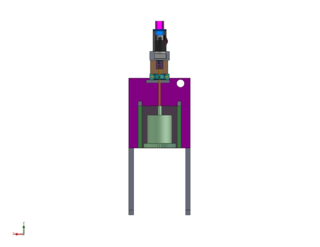
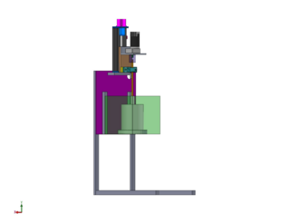
| − | + | The preliminary designs were first created in SolidWorks. Below are the designs; two aluminum sheets (tan) will be attached to the stepper motor, an angled aluminum sheet (gray) will attach the DC motor to the stepper, a sheet will attach the bearing to the stepper, and finally a coupling (purple) will attach the rotation rod (gold) to the DC motor with a separate coupling piece (green) for the DC motor. | |
{| border="0" style="text-align:center;" width="80%" | {| border="0" style="text-align:center;" width="80%" | ||
|- | |- | ||
| − | | style="width: 33%;" | [[File:Assembly_CrystalGrow_MC&RT_v1(Front).png|thumb|center|320px| | + | | style="width: 33%;" | [[File:Assembly_CrystalGrow_MC&RT_v1(Front).png|thumb|center|320px|]] |
| − | | style="width: 34%;" | [[File:Assembly_CrystalGrow_MC&RT_v1(R.Angle).png|thumb|center|320px| | + | | style="width: 34%;" | [[File:Assembly_CrystalGrow_MC&RT_v1(R.Angle).png|thumb|center|320px|]] |
| − | | style="width: 34%;" | [[File:Assembly_CrystalGrow_MC&RT_v1(L.Angle_NoOven).png|thumb|center|320px| | + | | style="width: 34%;" | [[File:Assembly_CrystalGrow_MC&RT_v1(L.Angle_NoOven).png|thumb|center|320px|]] |
| | | | ||
|} | |} | ||
| − | == Mechanical Setup == | + | ===Mechanical Setup=== |
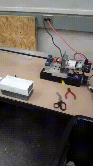
| − | + | The SolidWorks designs were then used as templates to create the first setup. | |
{| border="0" style="text-align:center;" width="80%" | {| border="0" style="text-align:center;" width="80%" | ||
|- | |- | ||
| − | | style="width: 33%;" | [[File:Movement.gif|thumb|center|320px|<text>]] | + | | |
| + | | style="width: 33%;" | [[File:Movement.gif|thumb|center|320px|This is a gif of the most current state of the setup with full rotation and translational movement(Watch in full resolution for animation)]] | ||
| + | |- | ||
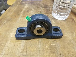
| + | | style="width: 33%;" | [[File:CS1.jpg|thumb|center|320px|Standard 1/2" pillow block bearing]] | ||
| + | | style="width: 33%;" | [[File:CS2.jpg|thumb|center|320px|Support piece for the bearing]] | ||
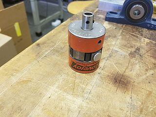
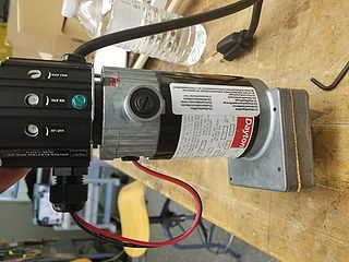
| + | | style="width: 33%;" | [[File:CS3.jpg|thumb|center|320px|Two L0076 sintered iron jaw couplig hubs, a L075 buna Nspider insert, and a coupling holder attachment that was created to attach the coupling to the DC motor.]] | ||
| + | |- | ||
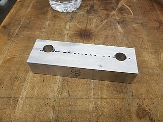
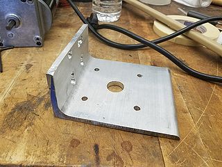
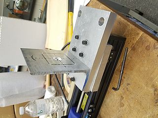
| + | | style="width: 33%;" | [[File:CS4.jpg|thumb|center|320px|The aluminum angle piece that holds up the DC motor]] | ||
| + | | style="width: 33%;" | [[File:CS5.jpg|thumb|center|320px|The 3/8" screws that bolt the setup to the stepper motor]] | ||
| + | | style="width: 33%;" | [[File:CS6.jpg|thumb|center|320px|The bottom support plate of aluminum that creates separeation away from the stepper which increases our vertical range]] | ||
| + | |- | ||
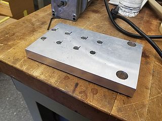
| + | | style="width: 33%;" | [[File:CS7.jpg|thumb|center|320px|The top support plate of aluminum that the angle sheet and bearing will attach to.]] | ||
| + | | style="width: 33%;" | [[File:CS8.jpg|thumb|center|320px|DC Gearmotor 90VDC]] | ||
| + | |- | ||
| + | |} | ||
| + | |||
| + | ===How to build mechanical setup=== | ||
| + | |||
| + | {| border="0" style="text-align:center;" width="80%" | ||
| + | |- | ||
| + | | style="width: 33%;" | [[File:CS9.jpg|thumb|center|320px|<br>'''Step 1:''' Screw in the two support plates and the angled piece. Screw tight all pieces except the top four screws (on the angled piece). There should be more "wiggly room" for the top 2 screws than the bottom.]] | ||
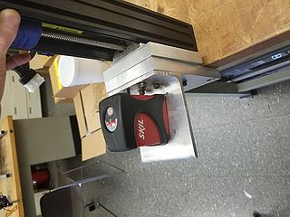
| + | | style="width: 33%;" | [[File:CS10.jpg|thumb|center|320px|<br>'''Step 2:''' Use the laser level and tighten only the bottom two screws on the angled piece to make sure it is parallel to the ground (do not tighten too much).]] | ||
| + | | style="width: 33%;" | [[File:CS11.jpg|thumb|center|320px|<br>'''Step 3:''' Screw in the DC motor with the brass screws (make sure that the center circular piece is in the hole of the angled piece). ]] | ||
| + | |- | ||
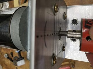
| + | | style="width: 33%;" | [[File:CS12.jpg|thumb|center|320px|<br>'''Step 4:''' Attach the coupling piece to the end of the DC motor. Use the tiny allen wrench to tighten (make sure the screw is lined up with teh flat surface). ]] | ||
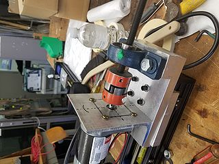
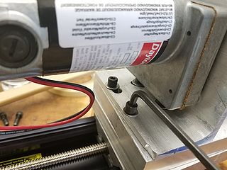
| + | | style="width: 33%;" | [[File:CS13.jpg|thumb|center|320px|<br>'''Step 5:''' First place the bearing support and bearing down with screws not tightened. Slide the shaft through the bearing and tighten with slightly thicker allen wrench at both the coupling and bearing (MAKE SURE THE SHAFT IS PUSHED AS FAR AS IT CAN INTO THE COUPLING!). ]] | ||
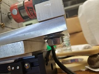
| + | | style="width: 33%;" | [[File:CS14.jpg|thumb|center|320px|<br>'''Step 6:''' Tighten bolts to back of screws under the support plate.]] | ||
| + | |- | ||
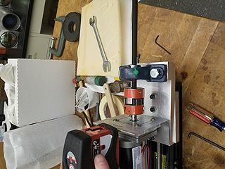
| + | | style="width: 33%;" | [[File:CS15.jpg|thumb|center|320px|<br>'''Step 7:''' Adjust the angled piece and bearing so that everything is lined up (you may have to losen then bolts below). ]] | ||
| + | | style="width: 33%;" | [[File:CS16.jpg|thumb|center|320px|<br>'''Step 8:''' Finally, tighten the top two screws on the angled piece with the allen wrench. Yay! You're done!]] | ||
| + | |} | ||
| + | |||
| + | ===Furnace Refurbishment and Setup [<font color="red">'''Refurbishment is completed and setup will be completed soon'''</font>]=== | ||
| + | |||
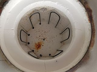
| + | To pack the material you simply wrap some of the insulation material around the q-tips (wood end) and lightly shove it into the holes around the heating elements. Repeat this procedure until you cannot fit any more insulation material inside the hole. A few things to note: do not push too hard so the elements do not break, make sure the hole completely around the elements are filled to maximum, and periodically check the top of the furnace where the electronics are to make sure the elements are still all even (they run through the furnace and are attached in pairs by two metal supports). | ||
| + | |||
| + | {| border="0" style="text-align:center;" width="80%" | ||
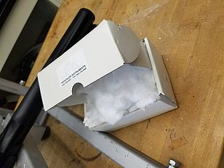
| + | | style="width: 33%;" | [[File:F1.jpg|thumb|center|320px|Element packing insulation material ]] | ||
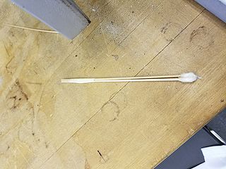
| + | | style="width: 33%;" | [[File:F2.jpg|thumb|center|320px|Two q-tips taped together were used to pack the insulation material around the heating elements.]] | ||
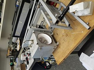
| + | | style="width: 33%;" | [[File:F3.jpg|thumb|center|320px|The furnace was placed on its side to more easily do the packing.]] | ||
| + | |- | ||
| + | | | ||
| + | | style="width: 33%;" | [[File:F4.jpg|thumb|center|320px|This is a view inside the furnace with five of the elements packed. ]] | ||
| + | |} | ||
| + | |||
| + | ===Furnace Operations=== | ||
| + | |||
| + | {| border="0" style="text-align:center;" width="80%" | ||
| + | | style="width: 33%;" | [[File:Control.png|thumb|center|320px|Furnace Control ]] | ||
| + | |} | ||
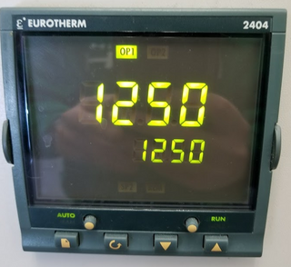
| + | First you must program the control. There are many options in customizing the operation of the furnace; this will discuss simply starting the furnace for a period of time then turning it off. | ||
| + | First click the far left button (the page icon) until Prog shows up and select List with the up and down arrows. Next, click the circular arrow buttom until Progn shows up and select the number of the program you wish to set. Click the circular arrow until all settings are as bellow… | ||
| + | • Hb: off | ||
| + | • HbU: 0 | ||
| + | • rmPU: Hour | ||
| + | • dwLU: Hour | ||
| + | • Cycl: 1 | ||
| + | The next few times you hit it will be for specific segments (called segn) of the total program | ||
| + | • Segn: 1 | ||
| + | • Type: step | ||
| + | • Tgt: desired temperature | ||
| + | • Segn: 2 | ||
| + | • Type: dwE11 | ||
| + | • Dur: # of hours | ||
| + | • Segn: 3 | ||
| + | • Type: step | ||
| + | • Tgt: 21 | ||
| + | • Segn: 4 | ||
| + | • Type: end | ||
| + | The program is now set, to run this program click the paper icon until run shows up then select list. Next click the circular arrow and select | ||
| + | • Prog: # of program you want to run | ||
| + | • Stat: run | ||
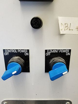
| + | Finally click the paper icon until you see the current temperature and the desired temperature below it. Turn the knob that is labeled element power on to start the heating. | ||
| + | {| border="0" style="text-align:center;" width="80%" | ||
| + | | style="width: 33%;" | [[File:Knobs.jpg|thumb|center|320px|Knobs to turn on control (left) and turn on heating elements (right) ]] | ||
| + | |} | ||
| + | | | ||
| + | |} | ||
| + | |||
| + | ===Temperature Profile [<font color="red">'''Will be changed'''</font>]=== | ||
| + | |||
| + | {| border="0" style="text-align:center;" width="80%" | ||
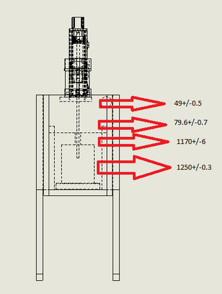
| + | |style="width: 33%;" | [[File:TempProfile.png|thumb|center|320px|These measurements are (from top down) at 18 inches, 15 inches, 12 inches, 9.5 inches, and 5 inches taken with respect to the bottom of the furnace.]] | ||
| + | |} | ||
| + | |||
| + | {| border="0" style="text-align:center;" width="80%" | ||
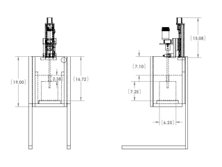
| + | |style="width: 33%;" | [[File:FurnaceMeasurement.png|thumb|center|320px|Dimensions of the furnace.]] | ||
| + | |} | ||
| + | |||
| + | ===Furnace Runs and Crystal Formation [<font color="red">'''Still in infancy stages'''</font>]=== | ||
| + | |||
| + | Need to check if the mechanical setup is safe at the current location and possibly cutting the insulator panels. Patrick needs to replace the wires with high-temperature ones. The hole in the furnace needs to be increased to .5". | ||
| + | |||
| + | {| border="0" style="text-align:center;" width="80%" | ||
| | | | ||
|} | |} | ||
Latest revision as of 13:35, 20 December 2017
Crystal Formation Designs and Creation [Currently Ongoing]
SolidWorks Design
The preliminary designs were first created in SolidWorks. Below are the designs; two aluminum sheets (tan) will be attached to the stepper motor, an angled aluminum sheet (gray) will attach the DC motor to the stepper, a sheet will attach the bearing to the stepper, and finally a coupling (purple) will attach the rotation rod (gold) to the DC motor with a separate coupling piece (green) for the DC motor.
Mechanical Setup
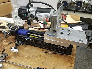
The SolidWorks designs were then used as templates to create the first setup.
How to build mechanical setup
Furnace Refurbishment and Setup [Refurbishment is completed and setup will be completed soon]
To pack the material you simply wrap some of the insulation material around the q-tips (wood end) and lightly shove it into the holes around the heating elements. Repeat this procedure until you cannot fit any more insulation material inside the hole. A few things to note: do not push too hard so the elements do not break, make sure the hole completely around the elements are filled to maximum, and periodically check the top of the furnace where the electronics are to make sure the elements are still all even (they run through the furnace and are attached in pairs by two metal supports).
Furnace Operations
First you must program the control. There are many options in customizing the operation of the furnace; this will discuss simply starting the furnace for a period of time then turning it off. First click the far left button (the page icon) until Prog shows up and select List with the up and down arrows. Next, click the circular arrow buttom until Progn shows up and select the number of the program you wish to set. Click the circular arrow until all settings are as bellow… • Hb: off • HbU: 0 • rmPU: Hour • dwLU: Hour • Cycl: 1 The next few times you hit it will be for specific segments (called segn) of the total program • Segn: 1 • Type: step • Tgt: desired temperature • Segn: 2 • Type: dwE11 • Dur: # of hours • Segn: 3 • Type: step • Tgt: 21 • Segn: 4 • Type: end The program is now set, to run this program click the paper icon until run shows up then select list. Next click the circular arrow and select • Prog: # of program you want to run • Stat: run Finally click the paper icon until you see the current temperature and the desired temperature below it. Turn the knob that is labeled element power on to start the heating.
Temperature Profile [Will be changed]
Furnace Runs and Crystal Formation [Still in infancy stages]
Need to check if the mechanical setup is safe at the current location and possibly cutting the insulator panels. Patrick needs to replace the wires with high-temperature ones. The hole in the furnace needs to be increased to .5".
